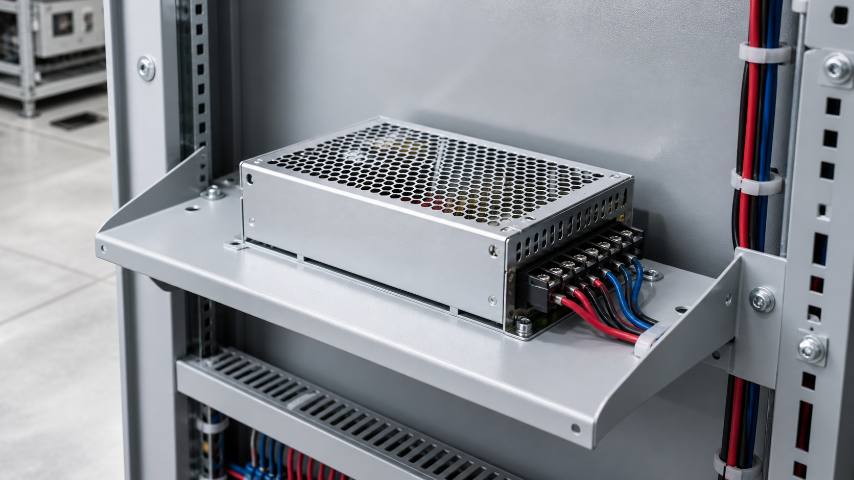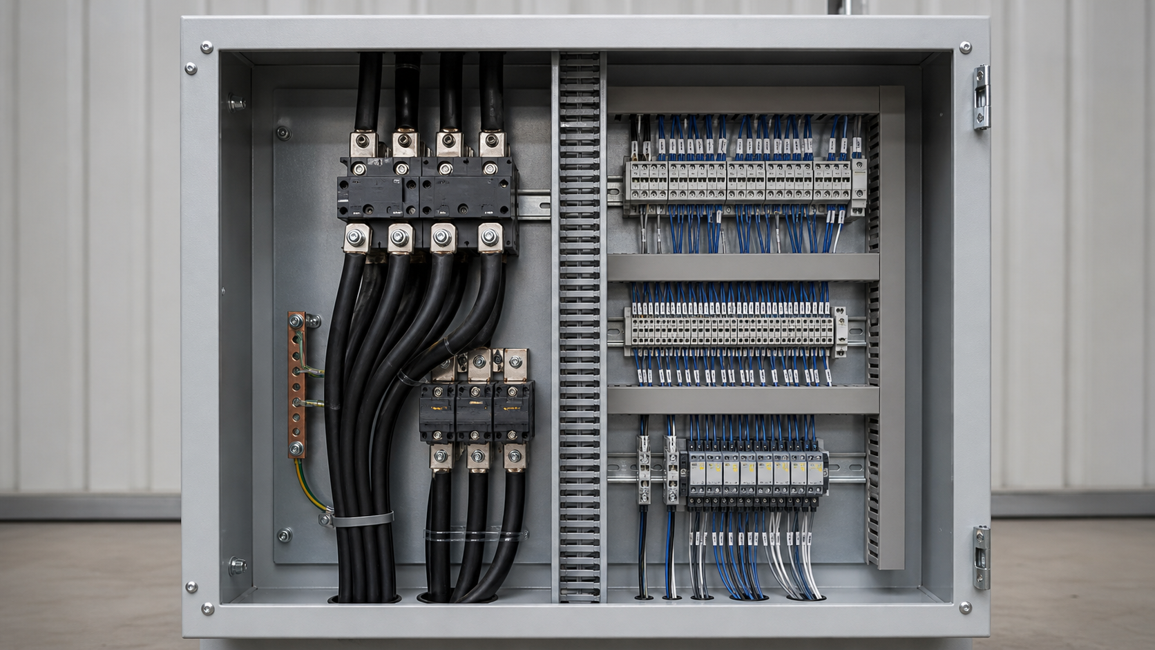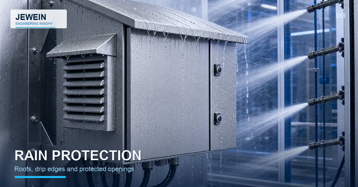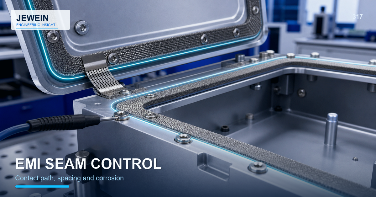



An enclosure corner concentrates several realities in one small area: bend radii, relief cuts, flange overlap, weld shrinkage, coating access, sealing, and visible alignment. If the corner is treated as two lines meeting in CAD, production may need filler, heavy grinding, or hand reshaping to make it look closed.
Strong sheet metal corner design selects a joint style around function first. Define which face controls appearance, how the flanges meet, what gap the process needs, where heat can escape, and how the finished corner will be inspected.
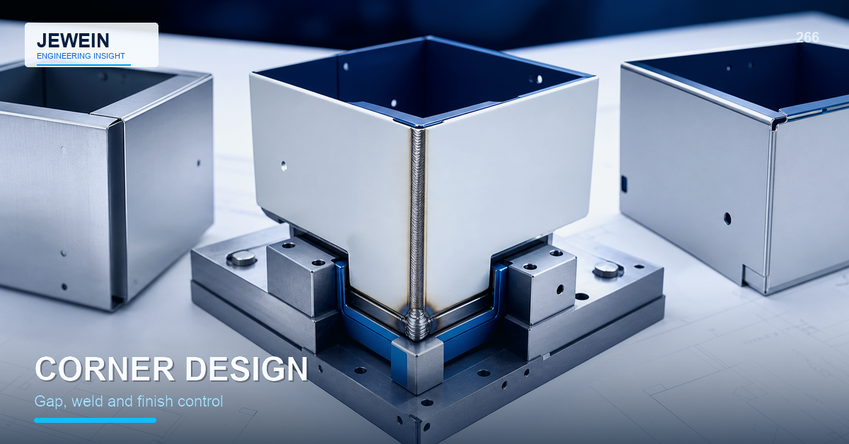
Choose a Corner Archetype Deliberately
| Corner type | Useful when | Risk to control |
|---|---|---|
| Open relieved corner | Drainage or low-cost closure matters | Sharp edges, visible gaps, and contamination |
| Edge-to-edge meeting flanges | Clean geometry and balanced faces | Gap sensitivity and weld access |
| Overlapping flange | Easy location or backing is useful | Step, trapped finish, and visible thickness |
| Tabbed or interlocking corner | Repeatable fit-up is important | Over-constraint and notch tearing |
| Welded and ground cosmetic corner | Seamless appearance is required | Heat distortion and excessive finishing |
| Sealed mechanical corner | Heat must be avoided | Sealant access, compression, and aging |
The right archetype depends on enclosure class, environment, quantity, finish, appearance, and repair needs.
Name the Controlling Face
At a visible corner, two panels rarely have equal priority. Decide which face must remain flush, which edge may show a small step, and where a weld or seam is acceptable.
Without that decision, a fixture may center the mismatch and leave both faces visibly wrong. A controlled face lets the supplier place normal variation where it causes less harm.
For doors and removable panels, review the corner in the complete gap pattern. The sheet metal door alignment guide shows why one local correction can move several surrounding relationships.
Give Bend Relief a Finished Purpose
Bend relief prevents tearing and flange interference, but its final opening also affects appearance, sealing, coating, and edge safety. Extend the relief enough for the bend to form, then review what remains after adjacent flanges close.
The sheet metal bend relief design guide explains the forming function. At the corner level, also check:
- whether the relief creates a pinhole or leak path;
- whether a weld can reach the root;
- whether coating can cover the cut edge;
- whether grinding removes too much parent material;
- whether a user can touch the exposed edge.
Set the Gap for the Joining Process
A zero-gap CAD corner may not assemble at zero gap. Cutting variation, bend angle, radius, springback, and flange position all affect fit-up.
Welding needs a gap and edge condition compatible with the joint and process. Too much gap demands filler and heat. Too little can prevent seating or move the part during clamping. Mechanical sealing needs space for the sealant bead and a geometry that can be cleaned and inspected.
Define the accepted pre-join condition separately from the finished appearance. That distinction prevents inspectors from rejecting a necessary process gap or accepting a finished void that should have been closed.
Control Heat and Grinding as a Pair
More weld metal usually means more heat and more finishing. Long continuous welds can pull thin corners, round crisp edges, and change adjacent panel flatness. Heavy grinding can thin the sheet, expose porosity, create waves, and change the visual radius.
Use suitable joint length, sequence, fixturing, cooling, and finish allowance. If sealing requires continuity, validate a route that achieves the seal without assuming the corner can absorb unlimited heat.
Retain an approved corner sample when appearance matters. Define lighting, viewing distance, allowed witness lines, and whether the corner is judged before or after coating.
Review Coating and Corrosion Paths
Overlaps and tight seams can trap pretreatment fluid, block powder, or create crevices. Ground welds may remove protective layers and require restored surface preparation. Sealants may be incompatible with pretreatment or curing temperature.
Inspect the complete corner after the final finish. Look for bridging, pinholes, exposed edges, trapped residue, cracks, and uneven build around the seam.
Use a Corner Approval Board
For each critical corner, keep:
- a section view showing flange relationship;
- the controlling cosmetic face;
- flat-state relief geometry;
- accepted pre-join gap;
- joining and sequence notes;
- grind or finish limit;
- seal and coating requirements;
- inspection views and approved sample;
- repair limits.
This board turns sheet metal corner design into a transferable manufacturing decision rather than operator preference.
Reapprove the sheet metal corner design if material thickness, relief geometry, welding process, coating, fixture, or cosmetic standard changes. Small upstream changes can alter both the pre-join gap and finished contour.
Jewein describes manufacturability and production-risk review in its company overview. Safety, sealing, structural, and environmental requirements still need product-specific qualification.
For a corner review, contact Jewein with the flat pattern, formed model, finish, joining process, appearance zone, seal requirement, quantity, and current defect photos.
Frequently Asked Questions
Why do sheet-metal corners develop gaps?
Bend relief, flange length, bend radius, material thickness, cut accuracy, sequence, and weld shrinkage can all change the final corner condition.
Should enclosure corners overlap or meet edge to edge?
The choice depends on appearance, sealing, weld access, strength, finishing effort, coating, and which surface must remain aligned.
How can corner grinding be reduced?
Use controlled gaps, accessible joints, appropriate weld size, fixtures, planned sequence, and geometry that does not require excessive filler or reshaping.
Do sealed corners need continuous welding?
The sealing method depends on the environment and requirement; continuous welding can also add heat distortion that must be controlled.
How should a finished corner be inspected?
Check gap, step, squareness, radius, weld and grind condition, coating coverage, seal continuity, sharp edges, and mating-panel alignment.