


A stainless-steel cover can be dimensionally correct and still be rejected because bright lines appear beside every bend. The marks may come from clean tooling under normal pressure, worn die shoulders, trapped grit, damaged film, or handling after the operation.
Press brake tool marks should be treated as a surface-control problem that begins before bending. Buyers and suppliers need to identify cosmetic faces, contact zones, acceptable appearance, protective methods, and inspection lighting before the first production batch.
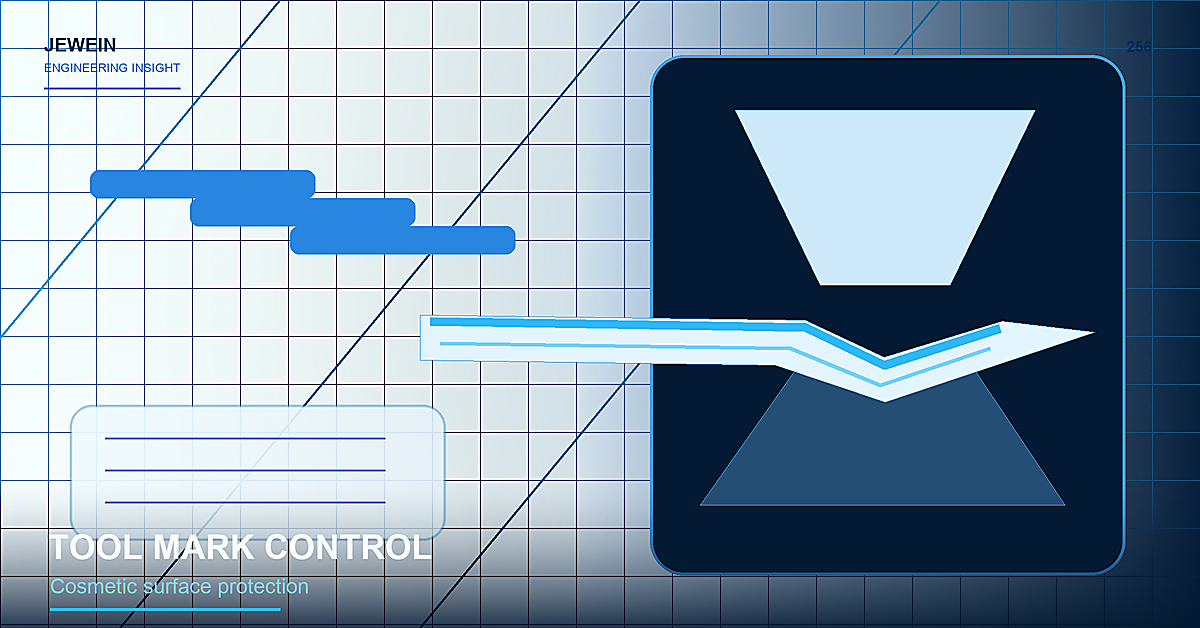
Diagnose the Mark Before Choosing a Fix
Different patterns point to different causes.
| Mark pattern | First checks | Possible control direction |
|---|---|---|
| Two straight lines along the bend | Die shoulders and sheet movement | Tool condition, film, protective insert, process review |
| Repeated scratch at one location | Burr, chip, damaged tool, dirty support | Clean and inspect contact surfaces |
| Random fine scratches | Handling, stacking, contaminated film | Material and work-in-process protection |
| Dull or polished band | Friction and pressure on directional finish | Tooling interface and face orientation |
| Dent or witness on opposite face | Punch contact, thin material, excessive force | Punch condition, support, bend method |
Do not cover the symptom with polishing until the source is known. Polishing can change grain, flatness, color, or edge detail.
Mark the Cosmetic Face on the Drawing
The supplier cannot protect a face that is not identified. Define:
- Class A or primary visible surfaces;
- secondary visible surfaces;
- hidden or non-cosmetic areas;
- brushed or directional grain;
- protective film requirements;
- allowed contact or rack locations;
- viewing distance, lighting, and angle;
- approved sample or defect standard.
Avoid phrases such as "no marks" without an inspection condition. Every manufactured surface has a condition; the goal is a measurable, commercially realistic boundary.
Follow the Surface Through the Entire Route
The mark blamed on bending may begin earlier or later. Review receiving, storage, cutting, deburring, bending, welding, cleaning, coating, inspection, packaging, and assembly.
The sheet metal deburring guide explains how burrs and sharp edges can damage nearby parts, film, cables, and finished surfaces. A burr on one blank can scratch several parts in a stack.
Evaluate Protection Methods as Process Changes
Film, urethane inserts, soft tooling interfaces, clean paper, tool coatings, and different bend orientation may reduce marking. They can also affect friction, bend angle, radius, repeatability, force, or contamination.
For each proposed method, confirm:
- compatibility with material and finish;
- effect on bend result;
- durability through the intended quantity;
- cleanliness and replacement frequency;
- risk of trapped particles or wrinkles;
- operator handling and setup time;
- effect on cost and lead time.
A protective layer is part of the forming process and should be validated with the product.
Tool Condition Needs a Visual Standard
Small dents, adhesive, embedded chips, rust, wear, or rough edges can repeat the same defect on every part. Clean tooling should be stored and inspected in a way that protects contact surfaces.
Create a simple check before cosmetic runs:
- wipe punch and die contact zones;
- inspect for chips, damage, and residue;
- confirm protective material condition;
- check supports and backgauges that touch the visible face;
- run and inspect the first representative part;
- stop after a new repeated line appears.
This prevents a full batch from copying one damaged contact point.
Bend Direction Can Move the Risk
Flipping the part may move die contact from a visible face to a hidden face, but it can also change grain orientation, bend sequence, handling, backgauge access, and dimensional control.
Review the complete operation instead of adding a blanket note to keep all visible faces upward. Complex enclosures may expose different faces at different bends.
The sheet metal bend sequence guide helps connect orientation, tooling access, collision risk, and inspection checkpoints.
Keep Film Under Control
Protective film can reduce handling and tooling marks, but only when it is clean, intact, compatible with bending, and removed at the correct time. Film may stretch near a bend, wrinkle under pressure, hide debris, leave adhesive, or age during storage and curing.
Specify whether film stays on during cutting and bending, whether it is removed before welding or coating, and who checks the surface after removal. Do not let film become the only inspection system.
Approve Appearance With Representative Parts
Run the actual material, finish direction, bend radius, tooling, protection, and sequence. Inspect both immediately after bending and after the remaining process steps.
An approval set should show:
- controlled face and orientation;
- accepted tool-contact region;
- lighting and viewing method;
- film or insert used;
- first-piece dimensions;
- appearance after cleaning or finishing;
- packaging protection;
- sample revision and date.
Retain a protected sample or high-quality photographs when the appearance cannot be expressed numerically.
Separate Cosmetic Repair From Production Control
Brushing, polishing, blending, or refinishing may recover a part, but repair can change grain, reflectivity, thickness, coating preparation, and labor cost. Define whether repair is allowed, where, by what method, and how the result is re-inspected.
The primary control should prevent repeated press brake tool marks, not normalize unrecorded rework.
Jewein describes an engineering-driven workflow that analyzes drawings, applications, manufacturability, and production risk before scale-up. The Jewein company overview provides that brand evidence. Appearance acceptance remains product-specific and should not be confused with structural or material-performance certification.
Buyers can contact Jewein with the material, finish, controlled faces, bend geometry, current mark pattern, lighting standard, and production quantity to review press brake tool marks and practical prevention options.
Frequently Asked Questions
Why do press brake tool marks appear?
The sheet contacts the punch, die shoulders, inserts, debris, or worn surfaces under high pressure during bending.
Can protective film prevent all bending marks?
No. Film can help, but it can tear, wrinkle, trap debris, change friction, or fail at high-contact areas.
Do soft tooling materials change bend accuracy?
They can affect friction, radius, force, repeatability, or surface appearance, so the complete process must be validated.
Should cosmetic surfaces be marked on the drawing?
Yes. Identify controlled faces, acceptable appearance, grain direction, film, viewing condition, and any process restrictions.
How should tool marks be approved?
Use representative material and finish, inspect under agreed lighting, and retain an approved sample or visual standard tied to the revision.