


A part may contain individually possible bends that cannot be completed in one practical order. After an early flange is formed, the next tool collides with the wall, the backgauge loses a reference, or the operator can no longer rotate the part safely.
The sheet metal bend sequence is the planned order of forming operations, including tool choice, orientation, gauge reference, handling, and inspection. It should produce the required final geometry without trapping the tool, damaging the surface, or losing control of important datums.
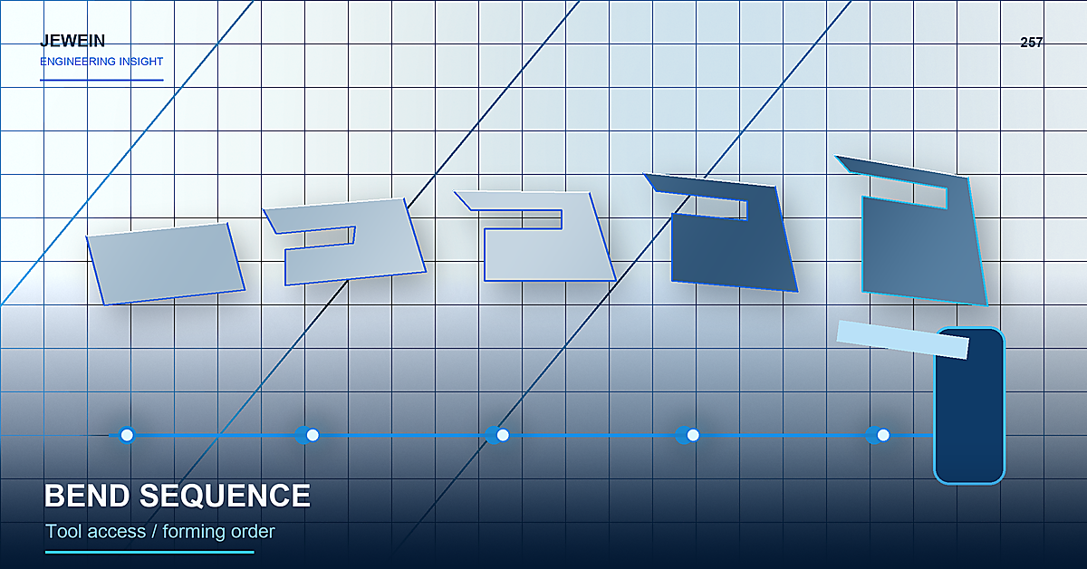
Use a Bend Storyboard, Not a Final Model Alone
Create one simple view for every bend state:
- flat blank and starting orientation;
- first bend with punch, die, and backgauge relationship;
- part after the first operation;
- approach and clearance for the second bend;
- remaining operations and part rotations;
- final unloading path;
- inspection checkpoints.
The storyboard reveals access problems that a finished 3D model can hide.
Start With the Most Restrictive Features
Identify bends constrained by:
- deep return flanges;
- narrow channels;
- tall walls;
- closed or nearly closed boxes;
- hardware installed before forming;
- cosmetic faces that cannot contact certain tools;
- short flanges that are difficult to gauge;
- bends near louvers, hems, or other formed details.
These features often determine the order. Flexible bends can then be arranged around them.
Track the Datum After Every Operation
A flat edge may be easy to gauge before forming and inaccessible afterward. A later bend may depend on a flange whose position already includes variation from an earlier angle.
For each operation, record:
| Bend step | Gauge or support reference | Critical result | Next risk |
|---|---|---|---|
| First | Stable flat edge | Initial flange position | Reference disappears after rotation |
| Middle | Formed flange or stop | Relationship to previous bend | Stack-up and springback |
| Late | Specialized support or gauge | Final opening or envelope | Tool and unloading collision |
This makes the accumulation path visible to design, production, and inspection.
Sequence Can Change Finished Relationships
Different orders can change how the part is supported, where variation accumulates, and which bend is compensated against another. If one bend is adjusted, a later flange may move even though its own program did not change.
The sheet metal bend allowance guide explains how flat development connects to the actual radius, material, and forming process. The springback control guide shows why measured behavior must be carried into repeat setup.
Include Tool Geometry in the Access Check
Nominal bend lines do not show the full punch, die, holder, machine frame, backgauge, support, and operator path. A gooseneck or narrow tool may create access, but it can introduce force, availability, marking, radius, or stability considerations.
Check:
- punch and holder clearance;
- die width and shoulder contact;
- machine open height and throat;
- backgauge reach;
- part support and balance;
- operator hand position and safe rotation;
- removal after the bend closes the shape.
Do not assume a special tool is available until the supplier confirms it.
Protect Cosmetic Faces During Rotations
Every rotation creates handling and support contact. Long or wide parts may drag across a table or rest on a newly formed edge.
Define protective film, clean supports, helper requirements, and controlled contact surfaces. The press brake tool marks guide provides a detailed method for diagnosing and preventing appearance damage during forming.
Decide When Secondary Operations Occur
Hardware, tapping, welding, deburring, countersinking, and formed features may need to happen before or after specific bends. Installing a fastener early can block tooling; installing it late can remove access for the press or installation anvil.
Add these operations to the storyboard. The manufacturing route is not only a list of bends.
Use Checkpoints Before Variation Multiplies
Inspect important relationships while they can still be corrected and while the datum remains accessible.
Useful checkpoints include:
- first bend angle and flange length;
- channel opening before closing returns;
- diagonal or parallelism before the final wall;
- hardware clearance before access disappears;
- cosmetic face condition after high-contact bends;
- final envelope and mating fit.
The checkpoint should protect the next operation, not duplicate final inspection without a decision.
Change the Design When the Route Is Fragile
If the only feasible sequence requires unstable gauging, unsafe handling, extreme tool access, or repeated hand correction, review the part design. Options may include changing a flange, adding a relief, splitting the part, using a joint, altering hardware timing, or adjusting a nonfunctional dimension.
Compare the effect on strength, appearance, sealing, cost, and assembly before approving the change. A manufacturable design is not automatically the best product design.
Release the Sequence With Repeat Setup Data
The production sheet metal bend sequence record should contain the operation order, tool set, orientation, gauge reference, program revision, part support, protective method, checkpoints, first-piece evidence, and any approved alternate route.
Jewein says its engineering-led process reviews applications and drawings, improves manufacturability, identifies production risks, and supports stable scale-up. The Jewein About page provides that context. The supplier normally owns detailed process planning, while the buyer retains authority over the finished product and safety requirements.
Buyers can contact Jewein with the model, material, bend table, difficult flange, cosmetic faces, hardware timing, and quantity for a focused sheet metal bend sequence review.
Frequently Asked Questions
Why does bend sequence matter in sheet metal?
Each bend changes the part shape, tool access, handling, datum availability, and risk of collision for the remaining operations.
Can the bend order change the final dimensions?
Yes. Different sequences can change how variation accumulates, where the part is gauged, and how springback or distortion affects later bends.
Who should define the bend sequence?
The supplier normally controls the process, while the buyer should define the finished requirements and approve design changes that affect function.
How can bend collisions be found early?
Review the part at every forming step with the intended punch, die, backgauge, machine space, orientation, and operator handling path.
How should a bend sequence be controlled?
Record the bend order, tool set, orientation, gauge references, checkpoints, program revision, and first-piece approval evidence.