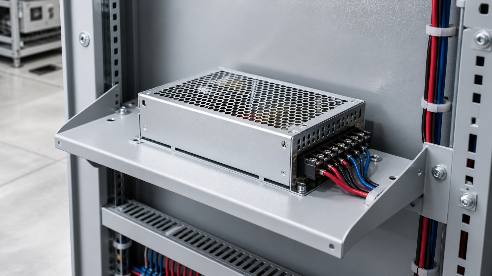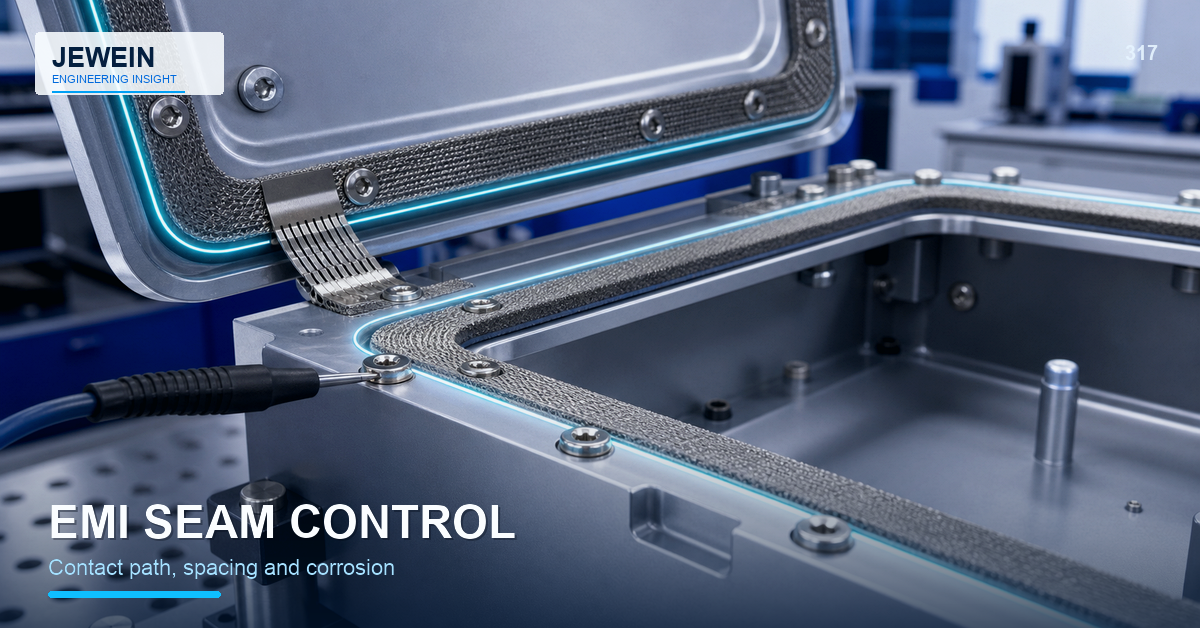



A coating line can produce an even, durable finish and still make the product impossible to assemble. Powder fills a thread, covers a grounding pad, narrows a hinge fit, or leaves an irregular border across a visible face. Masking must protect function without creating another corrosion or appearance problem.
Sheet metal powder coating masking should be planned from the finished assembly backward. The masking drawing needs to state what must remain uncoated, why it matters, how the boundary is located, who removes the mask, and how the exposed area will be inspected or protected.
Build a Functional Masking Map
Mark each protected area by function, not only color.
- Thread zones prevent powder from restricting screws or creating debris.
- Electrical contact zones preserve metal-to-metal conductivity.
- Bearing and hinge fits protect movement and alignment.
- Gasket surfaces control adhesion, compression, or sealing geometry.
- Datum and gauge areas keep inspection references usable.
- Identification zones preserve labels, marks, or later engraving.
- Weld or bonding zones may require a controlled bare surface.
Give each zone an owner and an acceptance check.
Define the Boundary From a Real Datum
"Mask around the hole" is ambiguous. State whether the boundary is controlled from the hole edge, center, hardware footprint, gasket path, or visible trim line. Complex shapes may need a drawing, template, plug, custom cap, or approved sample.
Consider coating buildup at the mask edge. A thick ridge can interfere with a mating part even when the bare area is correct. For visible boundaries, define acceptable feathering, edge shape, and orientation.
Choose Masking Materials for the Complete Process
The mask must survive cleaning, pretreatment, drying, powder application, curing temperature, handling, and removal. Common tools include plugs, caps, tapes, discs, custom shields, and reusable fixtures, but each has limitations.
| Masking method | Useful for | Review risk |
|---|---|---|
| Plug or cap | Holes, threads, studs, tubes | Wrong size, incomplete seating, removal damage |
| High-temperature tape | Flat boundaries and irregular shapes | Lift, residue, difficult repeat location |
| Die-cut disc or shape | Repeated pads and contacts | Alignment, edge ridge, adhesive life |
| Custom fixture or shield | High-volume repeated geometry | Tool wear, access, cleaning, revision control |
Validate the selected material with the actual pretreatment and cure cycle.
Threads Need More Than a Plug
A plug can keep powder out of the thread, but it must be installed to the correct depth and removed without leaving debris. Blind holes can also trap liquid or air during pretreatment and curing.
Check:
- whether the thread is cut before or after coating;
- plug type and depth;
- exposed lead-in requirement;
- drainage and venting;
- coating ridge near the entry;
- thread gauge and mating-screw test;
- contamination after mask removal.
The sheet metal clinch fasteners guide explains how finish sequence can affect installed hardware, threads, seating, and retention.
Grounding Points Need Product-Level Approval
An exposed metal pad may support electrical bonding, static discharge, shielding, or another design function. Its size, location, flatness, fastener pressure, corrosion protection, and verification method must come from the product requirement.
Do not create bare metal merely because a supplier expects a ground. Conversely, do not coat over a controlled contact because the finish looks more complete. The masking map should link the pad to the electrical design and final test.
This article does not assign electrical compliance or a protective-ground rating. Those claims require the applicable standard and qualified validation.
Protect Moving Fits and Gasket Interfaces
Coating can reduce clearance around hinges, slides, latches, pins, and close-fitting covers. It can also change gasket adhesion or compression.
Define the assembled state that must work after finish. Then decide whether to mask, increase design clearance, change the coating system, or install hardware afterward. The sheet metal enclosure gasket design guide provides a full-path method for reviewing geometry, hardware, coating, and compression together.
Control Exposed-Metal Risk
Masking removes protection from a selected surface. In a corrosive environment, the exposed edge or pad may need another treatment, conductive coating, sealant, protected hardware interface, or controlled service condition.
Review water traps, cleaning chemicals, condensation, dissimilar-metal contact, and whether the mask boundary sits under a gasket or outside the protected area. A bare pad that works electrically may fail environmentally if the surrounding product design ignores it.
Assign Installation and Removal Responsibility
State who applies each plug or tape, who checks it before coating, who removes it, and who verifies the final feature. Loose masks can contaminate the line; forgotten plugs can reach final assembly; aggressive removal can scratch a cosmetic face.
For reusable masking tools, control cleaning, wear, storage, and replacement. A cap that expands after repeated curing cycles may no longer protect the same boundary.
Inspect the Finished Function
The final audit for sheet metal powder coating masking should include:
- correct masked feature and boundary;
- no powder, residue, or damage in the protected area;
- acceptable coating edge and nearby appearance;
- thread, hinge, gasket, or contact function;
- exposed-metal protection where required;
- correct removal of all temporary materials;
- match to drawing, sample, and revision.
Use the actual mating screw, hardware, connector, or gauge when practical.
Release a Masking Control Package
Retain the drawing, zone purpose, datum, mask material and size, application photo, cure compatibility, removal method, functional check, approved sample, and change trigger. This makes the requirement repeatable across operators and coating suppliers.
Jewein describes its approach as combining drawing analysis, application review, manufacturability, production-risk identification, and scalable process planning. The Jewein About page provides that verified context. The buyer remains responsible for electrical, sealing, safety, corrosion, and regulatory requirements.
Buyers can contact Jewein with the coating system, mask drawing, functional surfaces, hardware, environment, quantity, and observed assembly problem for a practical sheet metal powder coating masking review.
Frequently Asked Questions
What areas should be masked before powder coating sheet metal?
Common areas include threads, electrical contacts, close fits, gasket surfaces, bearing locations, identification areas, and surfaces that must remain conductive.
Can coating thickness close a threaded hole?
Yes. Powder buildup can restrict threads, reduce clearance, and create debris if the thread is forced after curing.
Should grounding points be masked?
Masking may be required where the final assembly needs metal-to-metal electrical contact, but the exact requirement belongs to the product design and compliance plan.
Who should define the masking drawing?
The buyer and supplier should agree the functional surfaces, mask boundaries, tolerances, materials, removal responsibility, and inspection method.
How is powder-coating masking inspected?
Check boundary location, coverage, residue, thread and fit function, exposed-metal protection, hardware condition, and final assembly performance.