


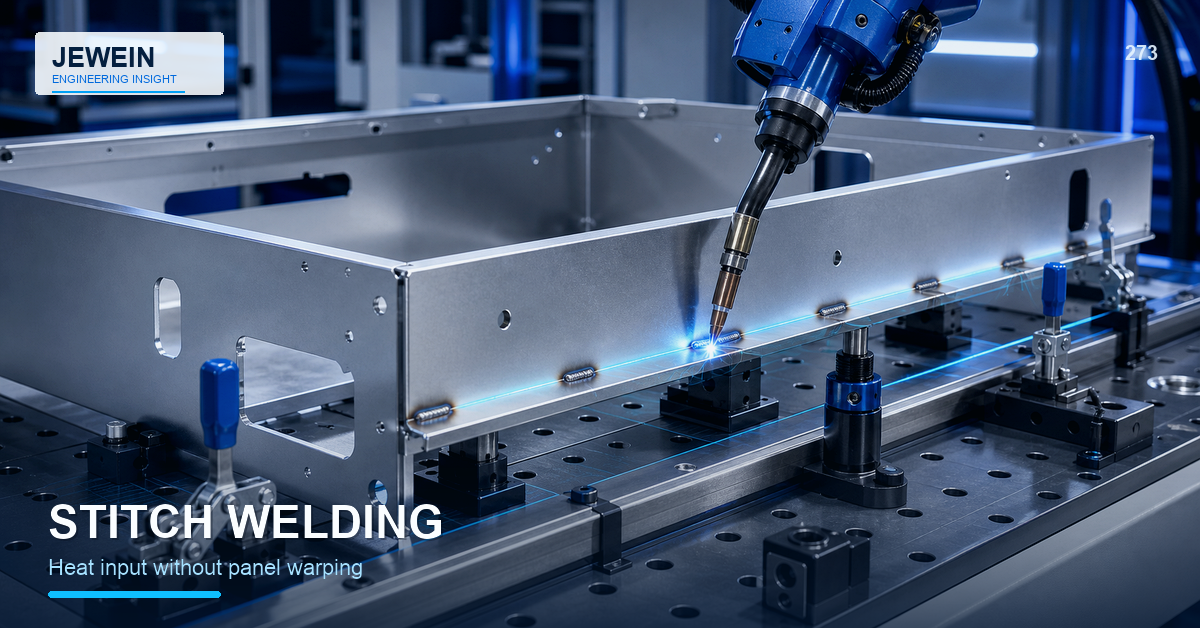
Intermittent weld segments can reduce total heat and finishing work compared with one continuous seam, but the pattern still creates shrinkage at every start, stop, and segment. Poorly selected length, pitch, order, restraint, or gap can leave a wavy flange, open joint, weak load path, or cosmetic print-through.
Plan stitch welding sheet metal with a thermal map and a functional joint map. Decide where the assembly actually needs attachment, then prove the segment pattern and sequence on a representative structure instead of copying a standard-looking pattern onto the drawing.
Separate Structural Need From Visual Habit
First define what the joint must resist: shear, peel, vibration, buckling, racking, handling, or local load transfer. Identify where forces enter and where panels can separate.
A row of equal segments may look orderly but provide little benefit in low-load areas while missing a stiffness transition or joint end. End conditions, corners, openings, brackets, and load introduction points often deserve different attention from the middle of a long flange.
Use a marked-up section or simple load sketch to explain why the segments exist.
Draw a Thermal Map Before the Sequence
Each segment adds a local heat zone and shrinkage vector. Plot the segments on the assembly and note:
- proximity to free edges and corners;
- nearby bends, embosses, holes, and hardware;
- large unsupported cosmetic surfaces;
- joint gaps and stiffness changes;
- fixture contacts and clamps;
- heat-sensitive components or coatings;
- locations that are difficult to straighten or grind.
The map helps the team see where heat will accumulate and where movement has room to develop.
Treat Length and Pitch as Independent Decisions
Segment length controls the local weld event. Pitch or spacing controls how those events interact along the joint.
| Pattern choice | Potential benefit | Potential risk |
|---|---|---|
| Shorter segments | Lower local heat, less finishing | More starts and stops, inconsistent fusion |
| Longer segments | Fewer transitions, more continuous attachment | Greater shrinkage and surface marking |
| Closer pitch | More attachment points | Heat interaction, cycle time, distortion |
| Wider pitch | Less heat and work | Panel movement, peel, vibration, open gaps |
For stitch welding sheet metal, release both values and the actual joint extent. Do not rely on a note that says only "stitch weld" without defining what production must build.
Prove the Start-Stop Quality
Starts and stops can create underfill, overlap, crater, porosity, spatter, or inconsistent penetration. A pattern with many short segments increases the number of transitions.
Use representative samples to review the process at segment ends, not only the smooth center. If the joint is later ground, coated, sealed, or exposed to corrosion, inspect the finished transition as well.
The drawing should define whether segments may overlap, whether the order matters, and how a missed or short segment is handled.
Sequence Around Movement, Not Convenience
The fastest torch path may pull the assembly in one direction. Compare alternatives such as balanced sides, alternating zones, center-outward work, or separated cooling intervals where appropriate.
Record the sequence at a useful level. A buyer usually does not need every operator motion on the product drawing, but the qualified work instruction should preserve the order that produced acceptable shape.
Check the released part after unclamping. A fixture can temporarily hide bow or twist. The large sheet-metal panel flatness guide explains why broad surfaces can move after heat and restraint are removed.
Define What the Fixture May Correct
Clamps should establish repeatable fit-up and location, not force an unacceptable joint into an artificial position. Note which surfaces locate, which gaps are allowed, and which areas must float.
If the operator needs excessive leverage to close the joint, the problem may come from upstream cutting, forming, tolerance accumulation, or part handling. Review the sheet metal tolerance stack-up guide before adding stronger clamps.
Do Not Use Intermittent Welds as a Hidden Seal
Separated segments leave paths between them. Paint, powder, adhesive, seam sealer, or a gasket may cover the gap, but that does not automatically create a qualified environmental or pressure seal.
If the product needs liquid, dust, air, or contamination control, define the complete sealing system and test method. Keep structural attachment and sealing requirements separate enough that each can be verified.
Inspect the Pattern as a System
The inspection plan should check:
- correct joint and side;
- segment location and extent;
- weld length and pitch;
- start-stop condition;
- fusion evidence and visible defects;
- burn-through, undercut, or excessive buildup;
- released distortion and dimensional fit;
- grinding, coating, and cosmetic result;
- assembly function and access.
Use templates, gauges, photographs, or digital records when they improve repeatability. A single overall length measurement cannot prove that every segment is correctly placed.
Retain the Approved Thermal Trial
Keep the drawing revision, material and thickness, joint gap, fixture condition, segment pattern, sequence, process settings, inspection results, and released dimensions from the approved sample. This package helps separate later material or process drift from a design problem.
Jewein describes DFM, production-risk, and scalable-process review in its company overview. Final weld performance and safety decisions require qualified engineering and welding personnel.
For a focused stitch welding sheet metal review, contact Jewein with the joint sections, material, thickness, expected load, cosmetic surfaces, gap condition, fixture concept, current sequence, and distortion measurements.
Frequently Asked Questions
What is a stitch weld on a thin-metal assembly?
It is a series of separated weld segments rather than one continuous weld, used when the joint can meet function without continuous heat input.
Does intermittent welding reduce distortion?
It can reduce total heat, but distortion still depends on segment length, pitch, order, joint restraint, gap, material, thickness, and cooling.
Can separated welds seal an enclosure?
Separated welds do not create a continuous metal seal, so leak, moisture, contamination, and pressure requirements need another qualified solution.
How should a stitch pattern be shown on a drawing?
Define weld type, segment length, pitch or spacing, location, side, extent, and any sequence or finishing requirements without ambiguity.
How are intermittent welds inspected?
Check segment size and location, pitch, fusion evidence, starts and stops, undercut, burn-through, distortion, finish, and assembly fit.