


A correct symbol is compact; an incomplete symbol transfers a hidden design decision to the shop. If the drawing leaves joint side, weld type, size, length, pitch, contour, finish, extent, or sequence unclear, different suppliers can build different assemblies while believing they followed the same requirement.
Use sheet metal weld symbols as a translation between product function and one buildable joint. Review the symbol beside an enlarged section, confirm physical access, and connect it to acceptance evidence before release.
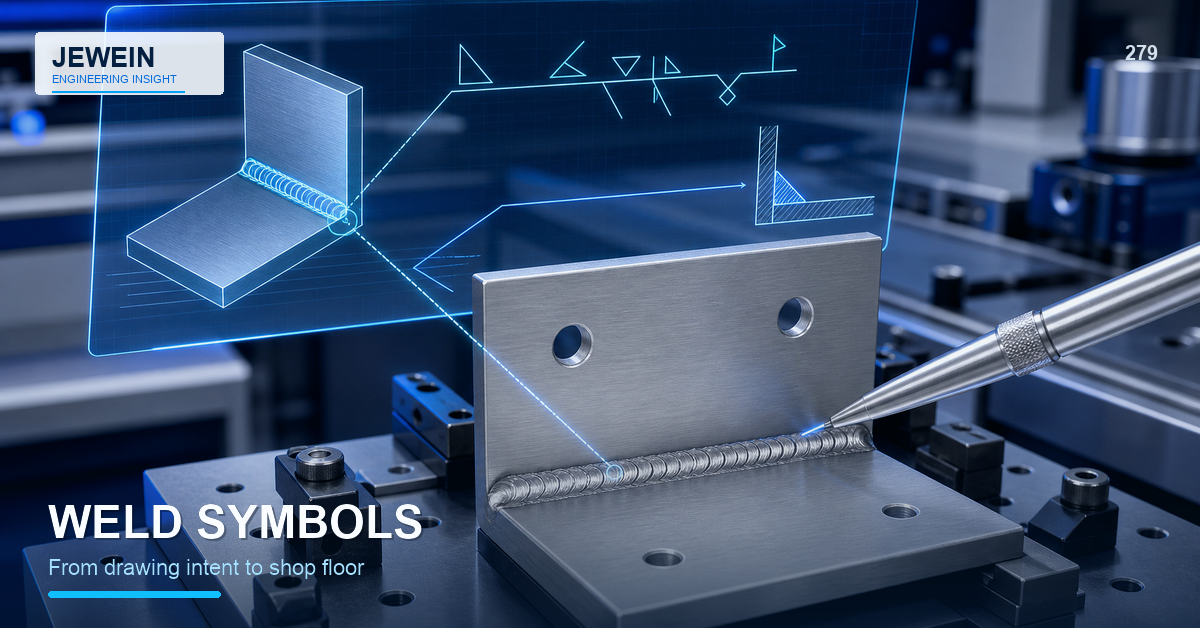
Begin With a Plain-Language Joint Statement
Before placing notation, write what the joint must do:
- attach this flange to this panel;
- carry shear and limit peel;
- maintain alignment at the mating surface;
- avoid heat marks on the visible face;
- use intermittent segments except at the ends;
- receive a flush finish only in the identified zone;
- remain inspectable after assembly.
The statement exposes missing decisions before they are compressed into symbols.
Translate One Section at a Time
Create an enlarged cross-section showing the actual parts, joint gap, material thicknesses, accessible sides, and nearby obstructions. Then translate each requirement.
| Drawing question | Shop-floor meaning |
|---|---|
| Which joint? | Exact parts and seam location |
| Which side? | Torch or electrode approach and deposited side |
| What type? | Fillet, groove, spot, seam, plug, or other defined joint |
| What size? | Required dimension and load intent |
| What extent? | Full length, segment length, pitch, count, or all-around path |
| What contour and finish? | As-welded, flush, convex, concave, and approved method |
| What reference? | Procedure, note, detail, or governing requirement |
Do not copy a symbol from a different joint merely because it looks similar on the page.
Confirm Arrow-Side Meaning Visually
The arrow and reference line communicate which side receives the weld according to the drawing convention. Assembly views can make that relationship hard to see, especially when the part is mirrored, rotated, or shown from several directions.
Place the symbol next to a section and, when useful, add a clear detail identifier. Ask a second reviewer to point to the physical weld location without explanation from the designer. If the answer is not immediate, improve the drawing.
Define Size From Function and Geometry
Weld size should not be a reflexive percentage of sheet thickness. Review load path, joint type, material, edge distance, access, heat input, distortion, penetration, process capability, and failure consequence.
For sheet metal weld symbols, confirm that the specified dimension can be measured or otherwise verified. A requirement that cannot be interpreted consistently by production and inspection is not complete.
Avoid oversizing "for safety." Excessive weld metal can increase heat, distortion, grinding, surface damage, and cost without improving the governing failure mode.
Distinguish Length, Pitch, Count, and Extent
Intermittent and spot patterns need more than a weld type. Define the segment length, center spacing or pitch, number where applicable, start and end boundaries, and whether the pattern is staggered or aligned.
The stitch welding guide explains how segment pattern and sequence affect heat and distortion. Use a detail when a short notation could be read in more than one way.
Use All-Around Requirements Carefully
An all-around indication can create a large heat and finishing commitment. Confirm that the joint truly needs welding around every connected edge and that the process can access corners and transitions.
For enclosures, separate structural attachment from sealing. A continuous symbol does not by itself define a leak requirement or test. The seam welding guide covers boundary and verification planning.
Specify Contour and Finish Without Hiding Risk
A flush contour may require grinding or machining. Define where the finish applies and what method is allowed when it matters. Review remaining weld, sheet thinning, cosmetic blending, corrosion protection, and inspection after finishing.
Avoid a blanket "grind smooth" note across every joint. Some welds should remain as welded, while visible areas may need an approved sample and controlled blend direction.
Keep Procedure Notes in the Right Place
The symbol can reference a process, procedure, sequence, or other requirement through the drawing's approved convention. Decide what belongs on the product drawing and what belongs in the controlled work instruction.
Product function, joint location, and acceptance should remain clear across suppliers. Machine settings, operator motions, and maintenance details usually belong in process documentation unless the design specifically depends on them.
Run a Symbol-to-Shop Review
Before release, have design, manufacturing, and inspection walk through each critical joint:
- identify the physical joint and side;
- state the weld type and extent;
- show how the equipment reaches it;
- explain the load and distortion concern;
- identify the acceptance evidence;
- confirm the finishing and coating route;
- define repair and reinspection;
- verify drawing revision and linked notes.
Record questions and update the drawing rather than relying on verbal clarification that may not reach the next shift or supplier.
Control Revisions Across Every Consumer
A weld-symbol change can affect fixture design, robot programming, work instructions, inspection plans, cost, cycle time, finish, and purchased hardware. Release the new revision as a coordinated package.
Remove obsolete prints and digital work instructions from use. If work in progress exists, document which revision applies and how partially completed assemblies are dispositioned.
Build an Acceptance Crosswalk
For every critical symbol, list the corresponding inspection evidence: location, dimension, visual criteria, segment pattern, contour, finished appearance, physical test, leak test, or dimensional result. This crosswalk prevents inspection from checking only what is easy to see.
Jewein describes drawing, feasibility, and production-risk review in its company overview. Drawing conventions and acceptance requirements should be approved by qualified engineering and welding personnel for the applicable product.
For a focused review of sheet metal weld symbols, contact Jewein with the assembly drawing, joint sections, material and thickness, load intent, cosmetic zones, weld process assumptions, and current inspection plan.
Frequently Asked Questions
What information does a welding symbol communicate?
It can define joint type, arrow side, other side, size, length, pitch, contour, finish, all-around extent, field work, and reference notes.
What is the difference between a weld symbol and welding symbol?
A weld symbol represents the weld type, while the complete welding symbol includes the reference line, arrow, tail, dimensions, and supplementary information.
Should weld size be based on sheet thickness?
Thickness is one input, but load path, joint type, material, access, distortion, appearance, process, and qualification also affect the requirement.
How should intermittent welds be dimensioned?
Define segment length and pitch or spacing using the drawing convention, and clarify location, extent, end conditions, and sequence when needed.
How can notation mistakes be prevented?
Review the actual joint in section, compare the symbol with accessible process direction, use one governing revision, and confirm acceptance requirements.