


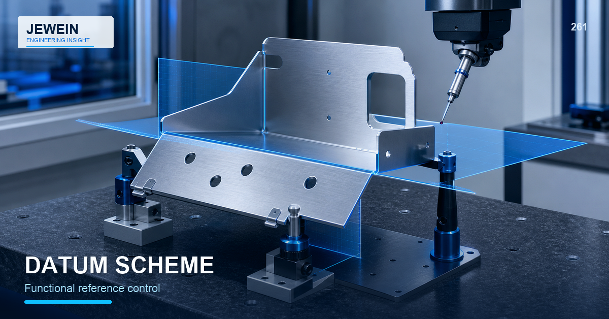
A sheet-metal part can pass a dimensional report and still rock in the fixture, pull a door out of alignment, or shift a connector away from its mating component. The problem is often not measurement capability. It is a reference scheme that does not represent how the part is located in the product.
A sheet metal datum scheme should constrain the same functional relationships that matter during assembly. Choose stable, accessible features; account for bend and flatness variation; define the datum order; and verify the scheme with representative formed parts rather than an ideal CAD surface alone.
Begin With the Six Motions the Assembly Must Stop
A free part can translate in three directions and rotate about three axes. The assembly, fixture, or mating hardware stops those motions through physical contact. Start the datum plan by identifying those contacts.
For example, an enclosure base may sit on mounting pads, locate laterally against two slots, and clock through one round hole. A door bracket may locate from a hinge face, a pin, and a stop. These are more useful starting points than selecting the largest surface automatically.
Write a plain-language locating statement before adding symbols:
- the part rests on these functional areas;
- this feature controls side-to-side position;
- this feature controls the remaining rotation;
- these holes, edges, or interfaces are then measured from that framework.
The statement gives design, manufacturing, and inspection teams one physical model to review.
Build a Functional Datum Chain
Use a chain that moves from product behavior to inspection evidence.
| Review point | Question | Useful evidence |
|---|---|---|
| Assembly contact | Where does the part actually touch? | Mating model, fixture, or marked-up assembly |
| Primary restraint | Which surface stabilizes the part first? | Contact area and support condition |
| Secondary restraint | Which feature controls lateral position? | Hole, slot, edge, or pin relationship |
| Tertiary restraint | What removes the final rotation? | Stop, hole, notch, or narrow face |
| Controlled feature | What must align after location? | Functional position, profile, gap, or envelope |
| Inspection method | Can the references be reproduced? | Fixture concept, CMM setup, gauges, and records |
This chain prevents a common disconnect: the drawing references one set of surfaces while the assembly relies on another.
Test Every Datum Feature Before Using It
A datum feature should be functional, repeatable, accessible, and sufficiently stable for the required decision.
Large sheet surfaces look attractive because they cover area, but they may contain bow, twist, weld distortion, coating buildup, or protective film. A narrow sheared edge may be easy to probe but may not control the installed position. A formed flange may be functional but can vary with angle, radius, and springback.
Review each candidate through four tests:
- Function: Does the product or mating component use this feature?
- Stability: Will normal process variation change the contact unpredictably?
- Access: Can production and inspection reach it after forming, welding, coating, and hardware installation?
- Transfer: Can a second supplier reproduce the same locating condition?
If one feature fails a test, the answer may be a datum target, a dedicated fixture pad, a different assembly interface, or a clarified inspection setup.
Datum Order Is a Physical Sequence
Primary, secondary, and tertiary references are not an alphabetical list. Their order describes how the part is constrained.
The primary feature usually establishes the most stable seating condition. The secondary feature removes additional motion without forcing the part away from the primary. The tertiary feature finishes location without over-constraining normal variation.
Problems appear when two rough formed edges are both treated as exact locators, when a long slot is used as though it fixed position in both directions, or when a flexible panel is clamped flat during inspection even though it floats in assembly.
The sheet metal tolerance stack up guide explains why the final relationship matters more than tightening every contributor. The datum order is the reference framework for that relationship.
Avoid Three Drawing Traps
Ideal planes that do not exist on the production part
CAD surfaces are perfectly flat. Fabricated panels are not. Define whether the inspection setup rests the part freely, supports specified areas, or applies an allowed restraint.
Redundant references that fight each other
Multiple holes, edges, and flanges may not all contact simultaneously. A fixture that forces every reference can hide the natural assembly condition or distort a thin part into compliance.
References lost after later operations
A datum may be covered by a bracket, distorted by welding, filled by coating, or blocked by hardware. Review the complete process route before release.
Convert the Datum Scheme Into a Measurement Plan
For each controlled feature, document:
- the datum simulator or fixture contact;
- free-state or restrained-state condition;
- support and clamp locations;
- probe or gauge access;
- surface condition, including coating or film;
- sequence of measurements;
- acceptance output and units;
- reaction when the part passes measurement but fails assembly.
The sheet metal inspection checklist can help connect this setup to first-piece and shipment records. Do not rely on a coordinate report that omits how the part was supported.
Validate With the Mating Condition
Use early formed parts to compare three results: fixture seating, dimensional data, and actual assembly fit. If the data predicts function, the scheme is useful. If it does not, investigate the references before tightening tolerances.
For flexible or welded parts, compare relaxed and installed states. For interchangeable components, test more than one part combination. Retain photographs of fixture contact, setup notes, and the approved revision.
Jewein describes its engineering process as reviewing drawings, manufacturing feasibility, production risk, and scalable process plans. The company overview provides that context. Final datum selection still depends on the product function, risk, and qualified engineering approval.
Review the sheet metal datum scheme whenever the mating design, fixture, forming route, or inspection equipment changes. A reference system that worked for one product revision may no longer predict the new assembly condition.
For a focused review of a sheet metal datum scheme, contact Jewein with the part drawing, mating model, assembly sequence, critical relationships, finish state, and current inspection method.
Frequently Asked Questions
Why are datums important on sheet metal drawings?
Datums establish the reference framework used to locate features, inspect the part, and connect dimensional results to assembly function.
Should a formed edge be used as a datum?
It can be appropriate when the formed edge consistently locates the assembly, but bend variation, edge condition, and inspection access must be considered.
Can the inspection datum differ from the assembly datum?
It can, but the drawing and inspection method should explain the relationship so a passing measurement still predicts assembly fit.
How many datum features should a sheet-metal part use?
Use enough references to constrain the required degrees of freedom without adding redundant controls that fight normal part variation.
How should a datum scheme be validated?
Locate representative parts in a fixture or mating assembly, compare functional results with measured data, and record the accepted setup and revision.