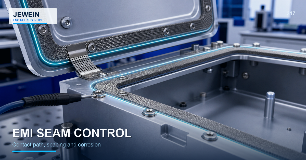



A metal enclosure may look continuous while its electrical path crosses paint, loose fasteners, hinges, sealants, corrosion products, and removable panels. Mechanical contact alone does not prove reliable continuity through production and service.
Design sheet metal grounding and bonding as a controlled path from the required conductive surface to the final ground or bond point. Identify every interface, decide how conductivity is created and protected, then test representative finished assemblies under the specified condition.
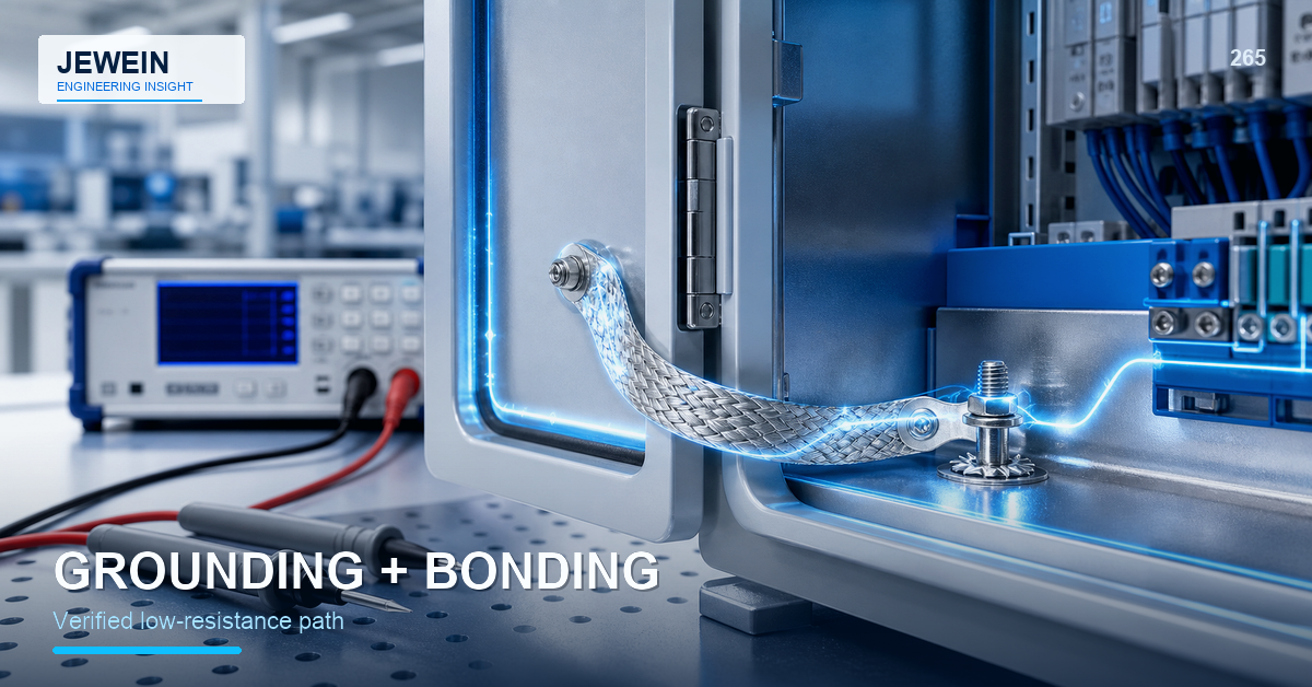
Trace the Current Path Physically
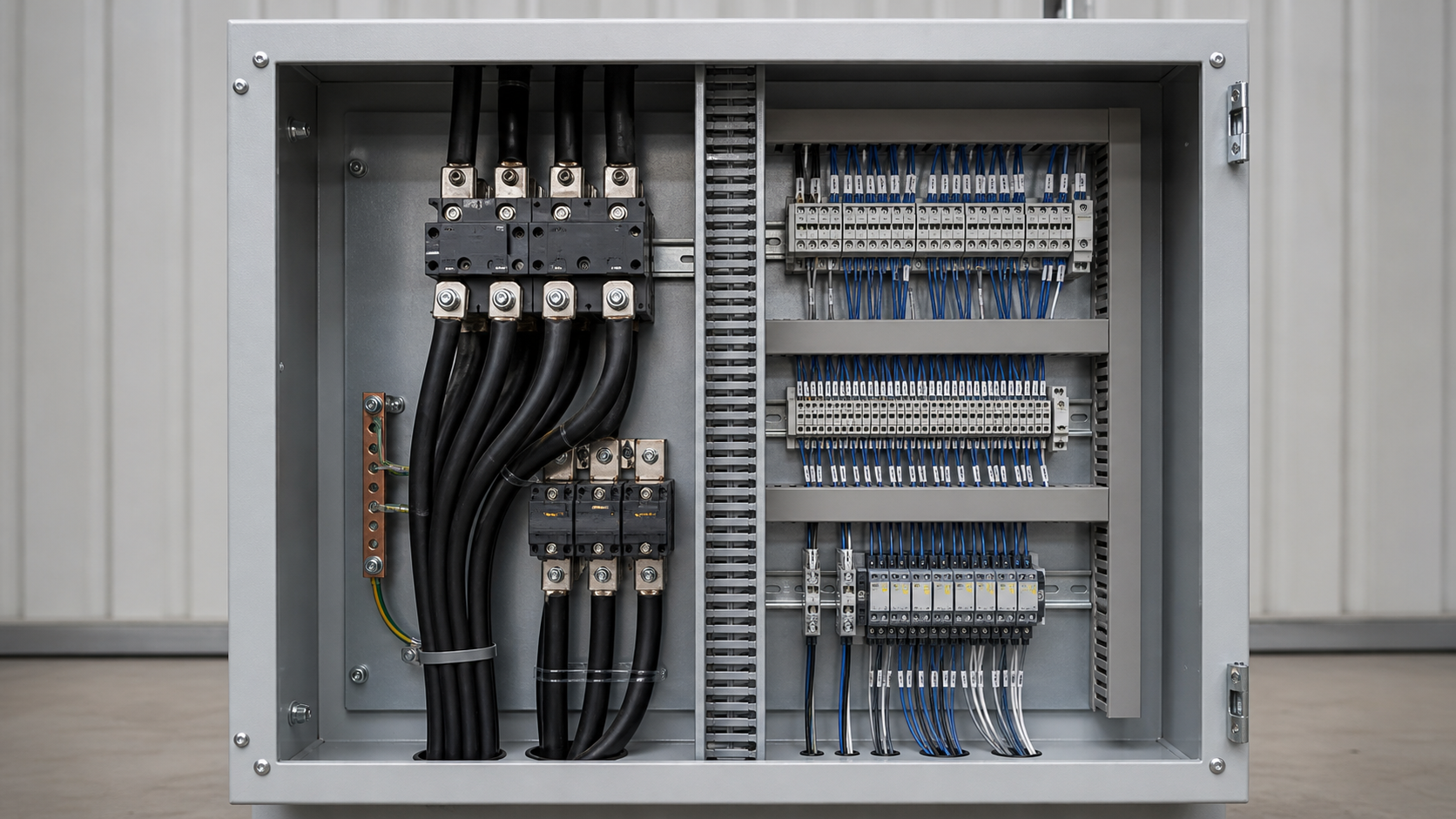
Begin at the component or panel that needs bonding and follow the path to its destination. Mark every transition:
- component to bracket;
- bracket to panel;
- panel to frame;
- frame to dedicated ground point;
- ground point to the external conductor or system.
At each transition, ask what surfaces touch, what hardware creates pressure, what coating is present, how corrosion is controlled, and whether the interface is disturbed during service.
This exercise often reveals that a nominally metallic route depends on one painted screw thread or a hinge that was never qualified as a conductor.
Run a Conductive-Path Audit
| Interface | Production risk | Service risk | Evidence |
|---|---|---|---|
| Bare metal contact | Oxidation or contamination | Corrosion over time | Surface specification and test |
| Masked coating area | Mask location or overspray | Exposed metal damage | Mask drawing and finish inspection |
| Fastener joint | Wrong hardware or low torque | Loosening and fretting | Hardware control and torque record |
| Hinge or moving joint | Variable contact | Wear, lubricant, and motion | Cycle test and alternate bond path |
| Welded interface | Spatter or incomplete joint | Corrosion at damaged finish | Weld and coating review |
| Bond strap | Routing or attachment error | Fatigue or service removal | Assembly instruction and continuity test |
The audit connects design intent to production controls instead of assuming conductivity.
Decide How Each Interface Becomes Conductive
Possible methods include direct prepared metal contact, conductive hardware, serrated contact features, dedicated studs, welded joints, qualified straps, conductive gaskets, or other approved interface materials.
Each method has limits. Serrations may cut coating but produce debris or inconsistent contact. A mounting screw can loosen or be replaced with a different finish. A welded path can be stable but may damage corrosion protection. A conductive gasket may depend on compression and surface cleanliness.
Select the method around the required electrical performance, environment, maintenance, and consequence of failure.
Control Paint Masking and Exposed Metal
If a bonding pad is masked, define its boundary, datum, size, surface preparation, allowed overspray, and protection after masking removal. A vague note such as "mask ground area" is difficult to inspect.
Exposed metal may corrode, collect fingerprints, or be damaged in transport. The design needs a compatible preservation and assembly plan. The sheet metal powder coating masking guide provides a method for assigning functional mask ownership.
If coating is intentionally pierced during assembly, validate the contact geometry and debris risk. Do not assume every tooth or washer will penetrate every coating thickness consistently.
Treat Hardware as Part of the Electrical Design
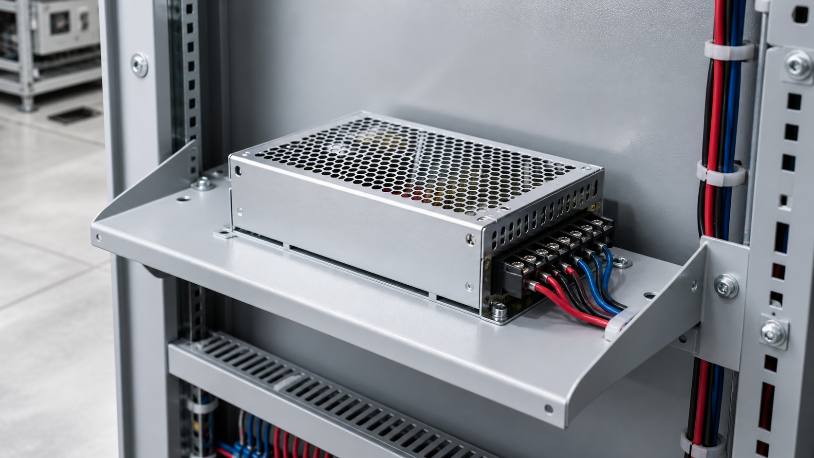
Control fastener material, plating, washer type, thread engagement, seating surface, and torque. Mixed metals can create corrosion concerns. Paint or sealant under a washer can change contact. A substitute screw may have a different coating or head interface.
For removable panels, decide whether the normal fasteners provide the bond or whether a dedicated strap maintains continuity before and after removal. Service instructions should preserve the intended hardware and sequence.
Review Seams, Doors, and Moving Interfaces
Doors and access panels often rely on hinges and latches mechanically. Their electrical behavior may vary with motion, lubricant, wear, contamination, and adjustment. If continuity is critical, a dedicated flexible bond may be more predictable.
Long seams can also affect shielding or current distribution. The appropriate interface spacing and compression depend on the actual electrical requirement. This article does not establish electromagnetic or safety limits; those belong to the qualified design and applicable test plan.
Test the Finished Assembly
Test after coating, hardware installation, and representative assembly. Define instrument setup, probe locations, contact preparation, acceptance limit, temperature or environmental condition, and whether moving panels are tested in multiple positions.
Consider initial production, after service cycles, and after environmental exposure when risk requires it. Record failures by interface so corrective action targets the actual path.
The sheet metal part marking guide can support identification of controlled bonding points and service components without relying on loose labels.
Release a Bonding Control Package
For reliable sheet metal grounding and bonding, retain:
- the marked current path;
- controlled contact surfaces;
- masking or surface-preparation drawing;
- approved hardware and torque;
- corrosion-protection method;
- assembly and service sequence;
- electrical test setup and limits;
- repair and rework instructions;
- revision and supplier applicability.
Repeat the sheet metal grounding and bonding audit after hardware substitutions, coating changes, seam redesign, or service-route updates. Each change can interrupt a path that previously passed testing.
Jewein describes drawing, process, and production-risk review in its company overview. Electrical safety, regulatory compliance, and required performance must be defined and approved by the responsible product engineering team.
For manufacturing review of a bonding interface, contact Jewein with the assembly drawing, finish, hardware, contact surfaces, environmental condition, service sequence, and required verification method.
Frequently Asked Questions
Why does paint interfere with sheet-metal bonding?
Most coatings separate conductive surfaces, so the design needs controlled contact areas, suitable hardware, or another qualified bonding method.
Can a mounting screw provide the grounding path?
It may contribute, but reliability depends on contact surfaces, hardware, pressure, corrosion, loosening, coating, and the required electrical performance.
Should bonding points be masked before powder coating?
Often they are, but exposed metal also needs a corrosion and handling plan, and the mask boundary must be clearly defined.
How should enclosure seams be bonded?
The method may use direct metal contact, conductive hardware, dedicated straps, welded joints, or qualified interface materials depending on the requirement.
How is bonding performance verified?
Use the specified electrical test method on representative finished assemblies and record the contact design, setup, limits, and corrective actions.